Introduction
Ohh boy its been a minute but progress is being made! This post will be a little longer than the others and also picture heavy, you’ve been warned! We last left off assembling the battery and testing. The battery has been finished and the BMS (Battery Management System) wired up and installed. Additionally most of the electronics have been mounted, ballast system fleshed out, and a fancy cover for everything printed. Let’s get to it!
Battery Continued…
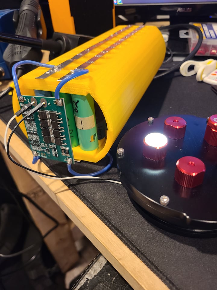
I drew inspiration for the battery pack design from Tesla. Each cell is connected to the bus bar with a fine nichrome wire. This wire will act as a fuse in the event a cell shorts hopefully preventing it from damaging the rest of the pack. Ideally a spot welder would be used for connecting these wires to the batteries (Tesla uses ultrasonic vibration) but I had to make due with the tools I have. With a hot soldering iron and brief contact you can safely solder wire directly to each cell.
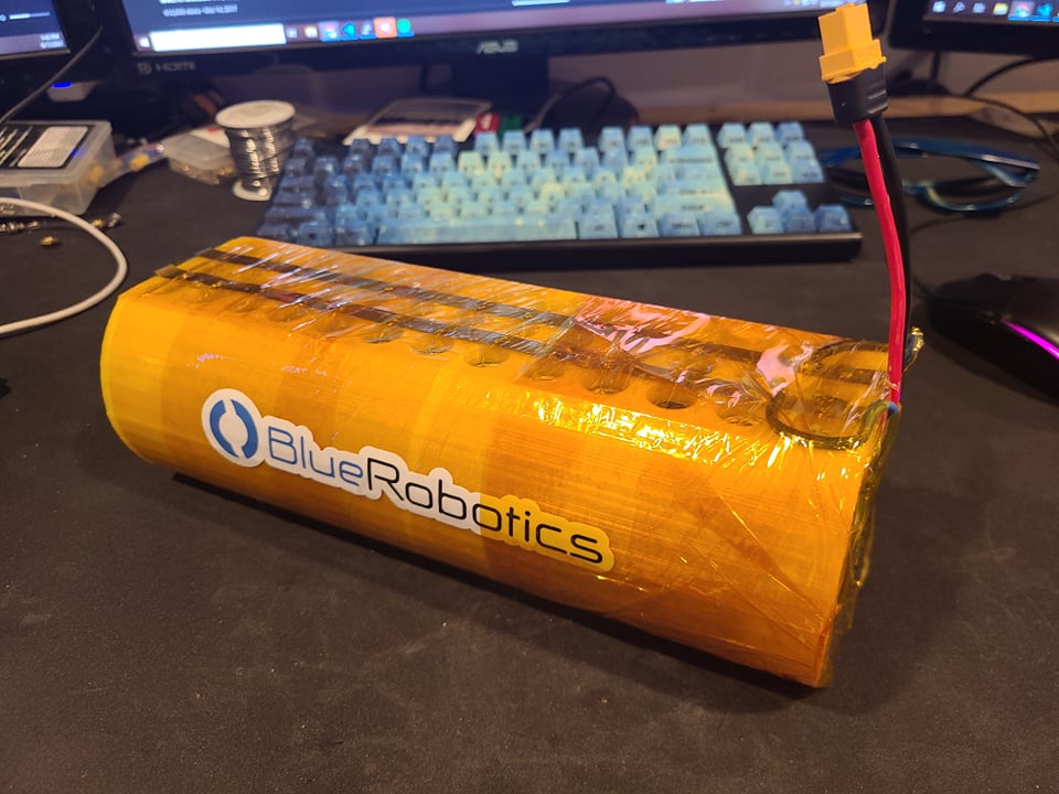
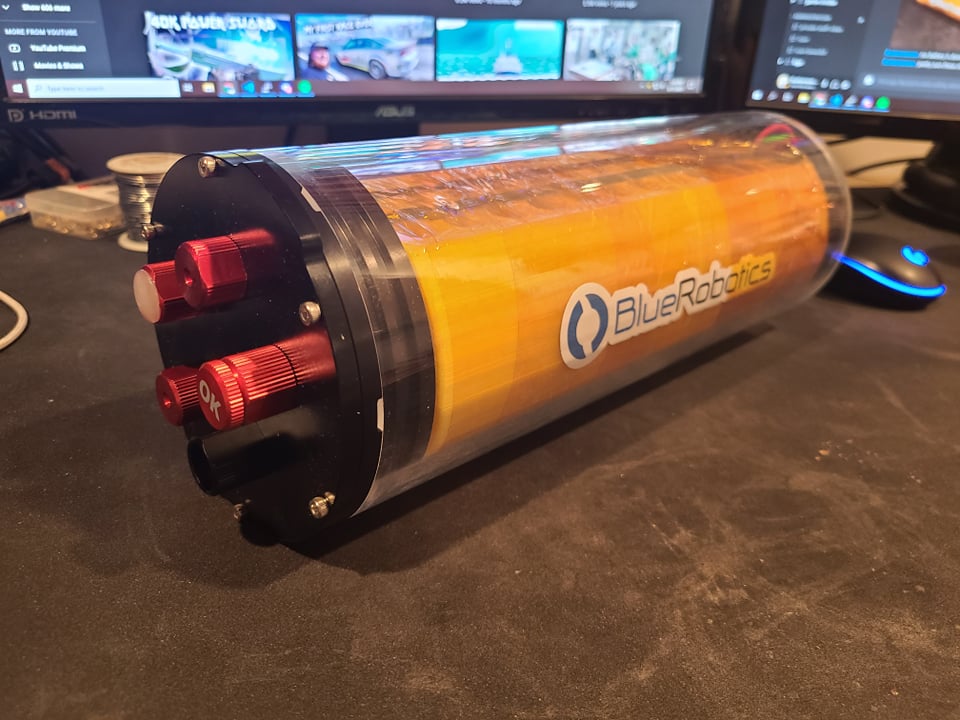
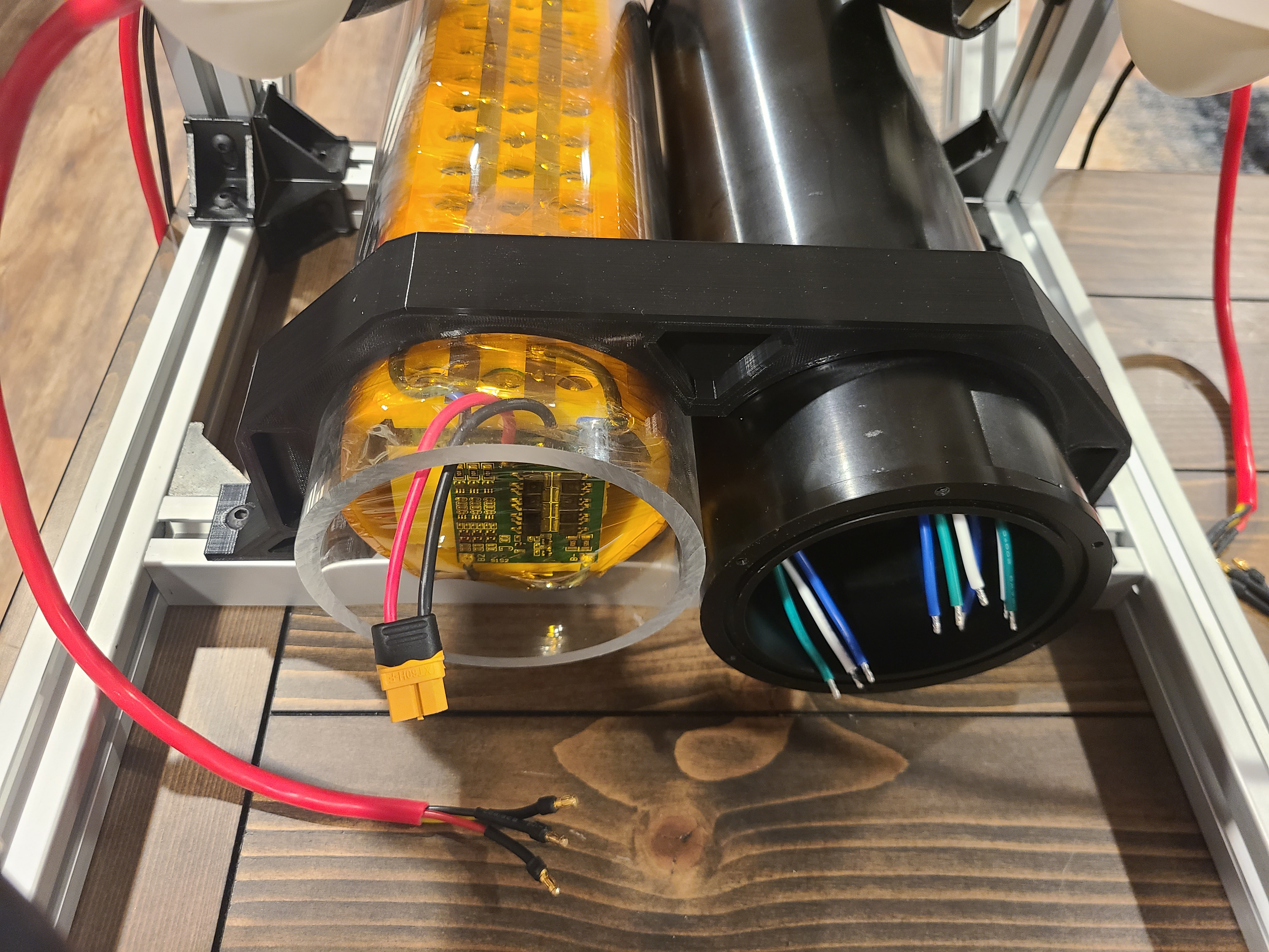
The whole pack was then wrapped in kapton tape for safety. In the event of any fire or heat this will hopefully isolate it and prevent a compromise in the structural integrity of the housing. Overall for this being a pack built of used cells, I am satisfied with its design and am optimistic in its ability to perform. Without putting it in its working environment its hard to know for sure.
Electronics Housing
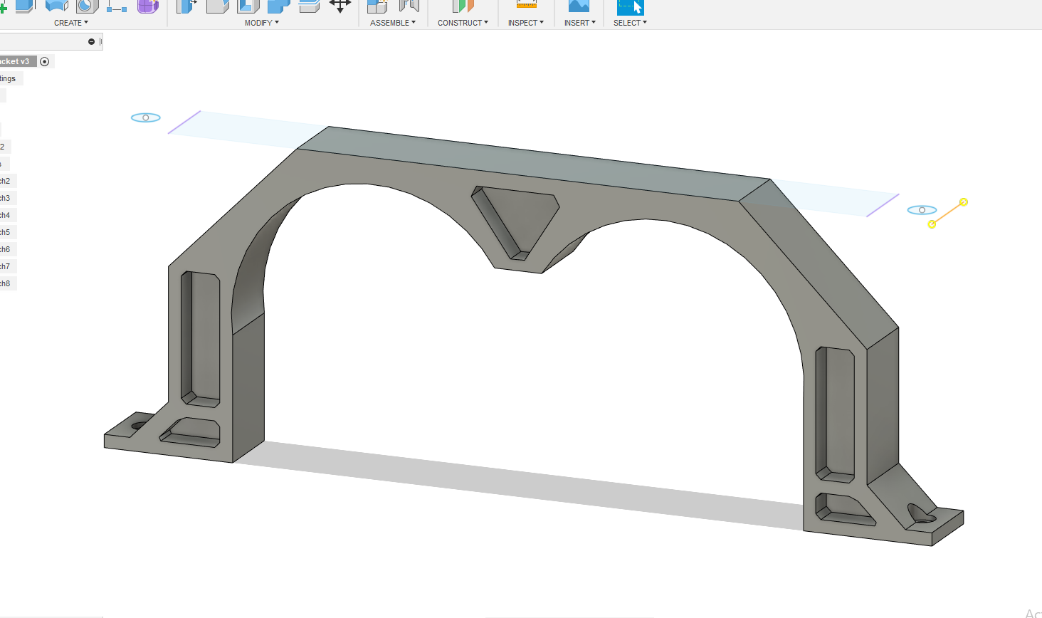
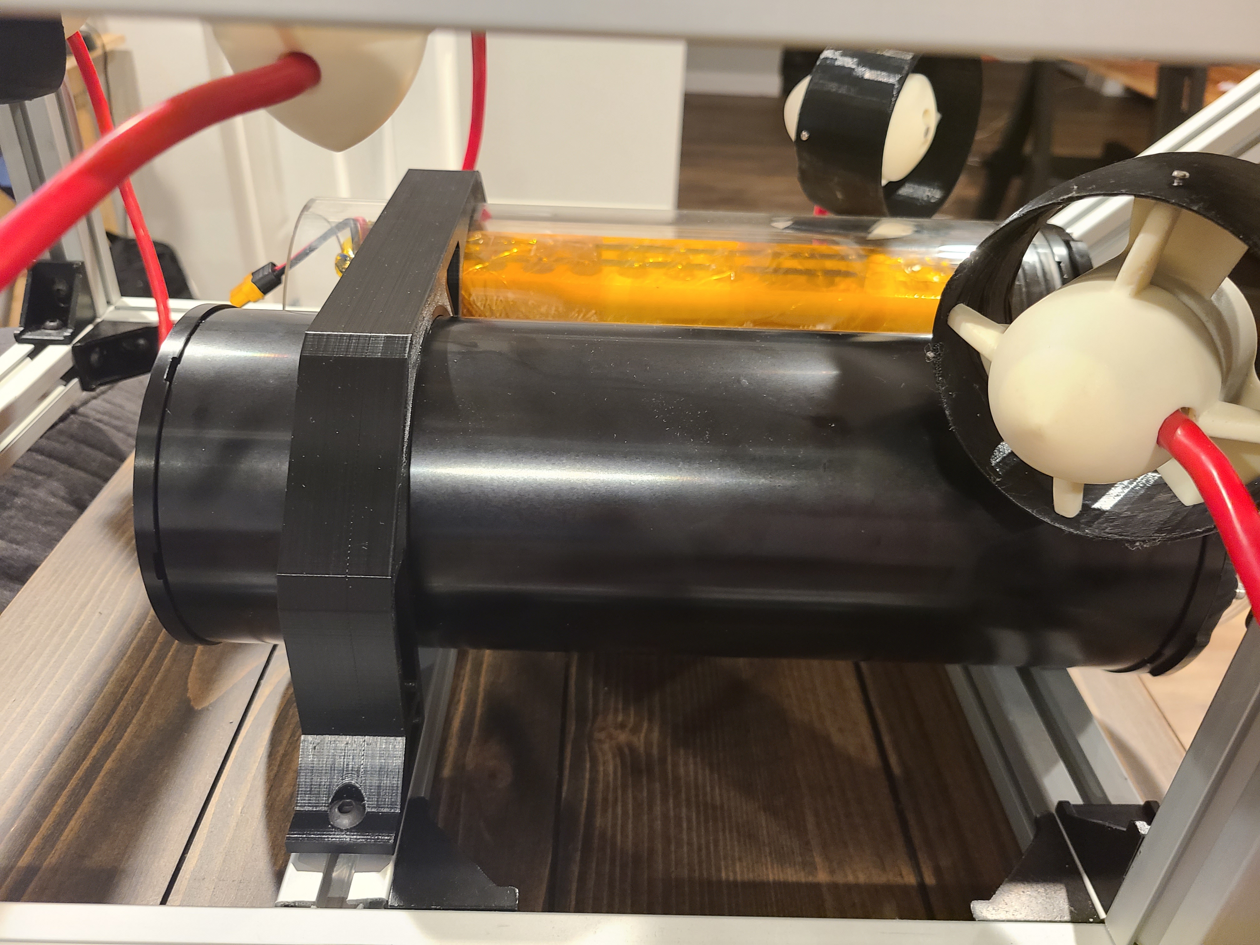
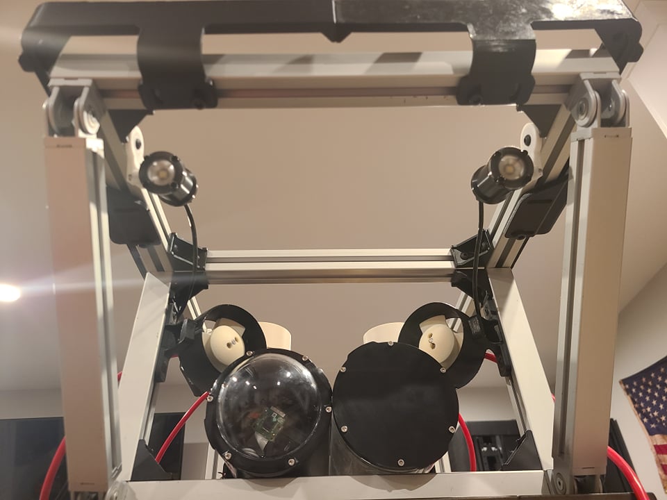
The next step was to find a mounting solution for the battery and electronics housings. I started learning Fusion360 and this seemed like a good opportunity to test my skills. This bracket tightly holds each housing to the frame and is easy to remove for maintenance. A few hours of printing later it was ready to install.
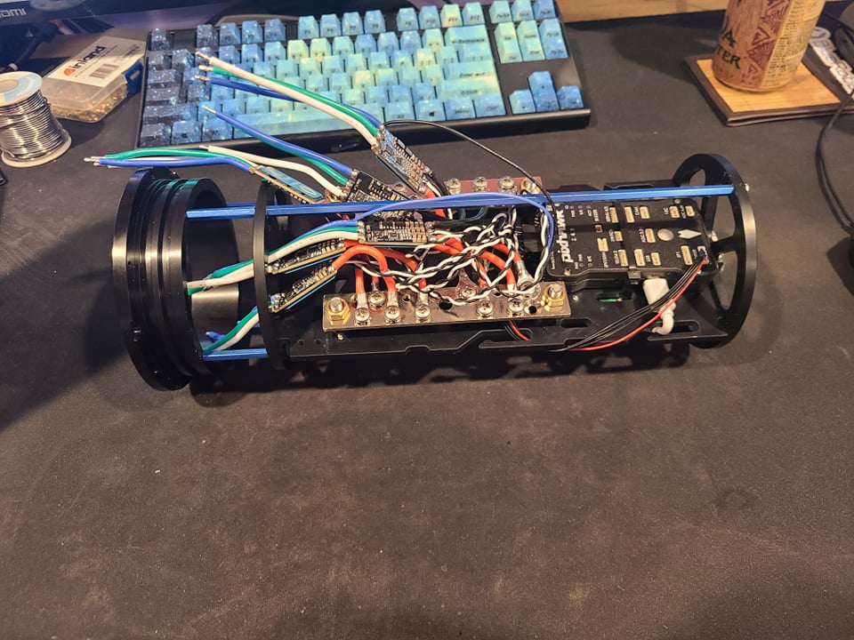
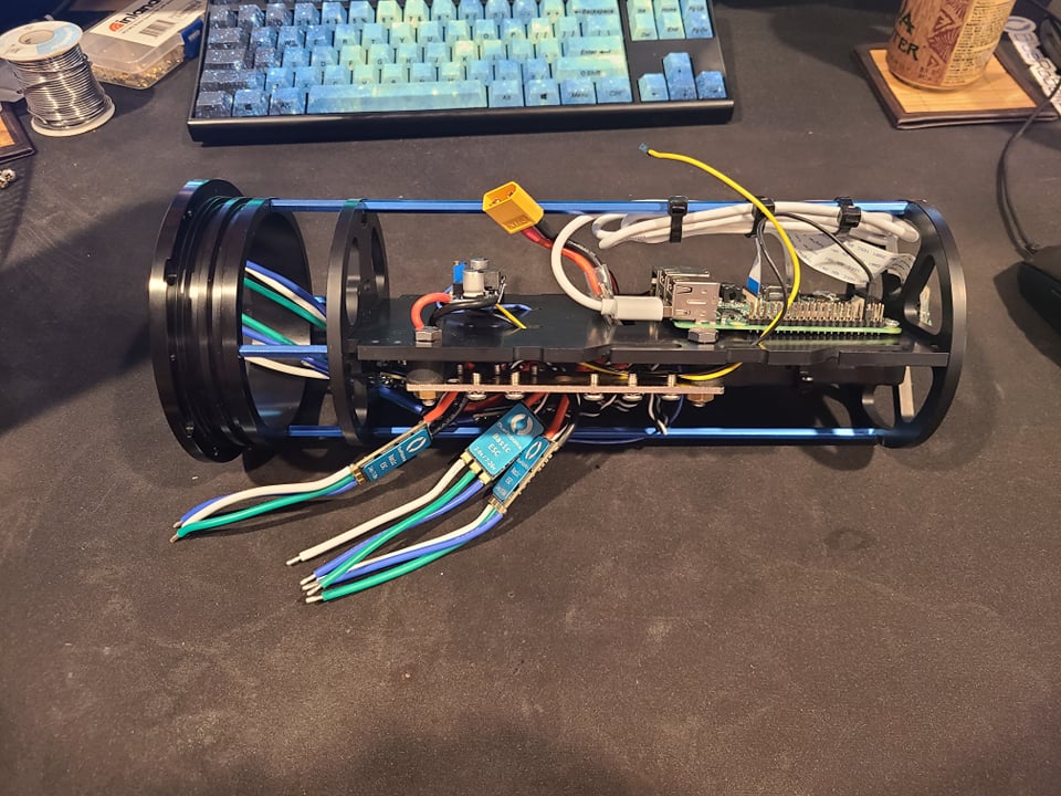
After this was completed I did some testing of different layouts for the pixhawk board and raspberry pi. The electronics tray is starting to become a little kaotic but hopefully some zipties will fix this.
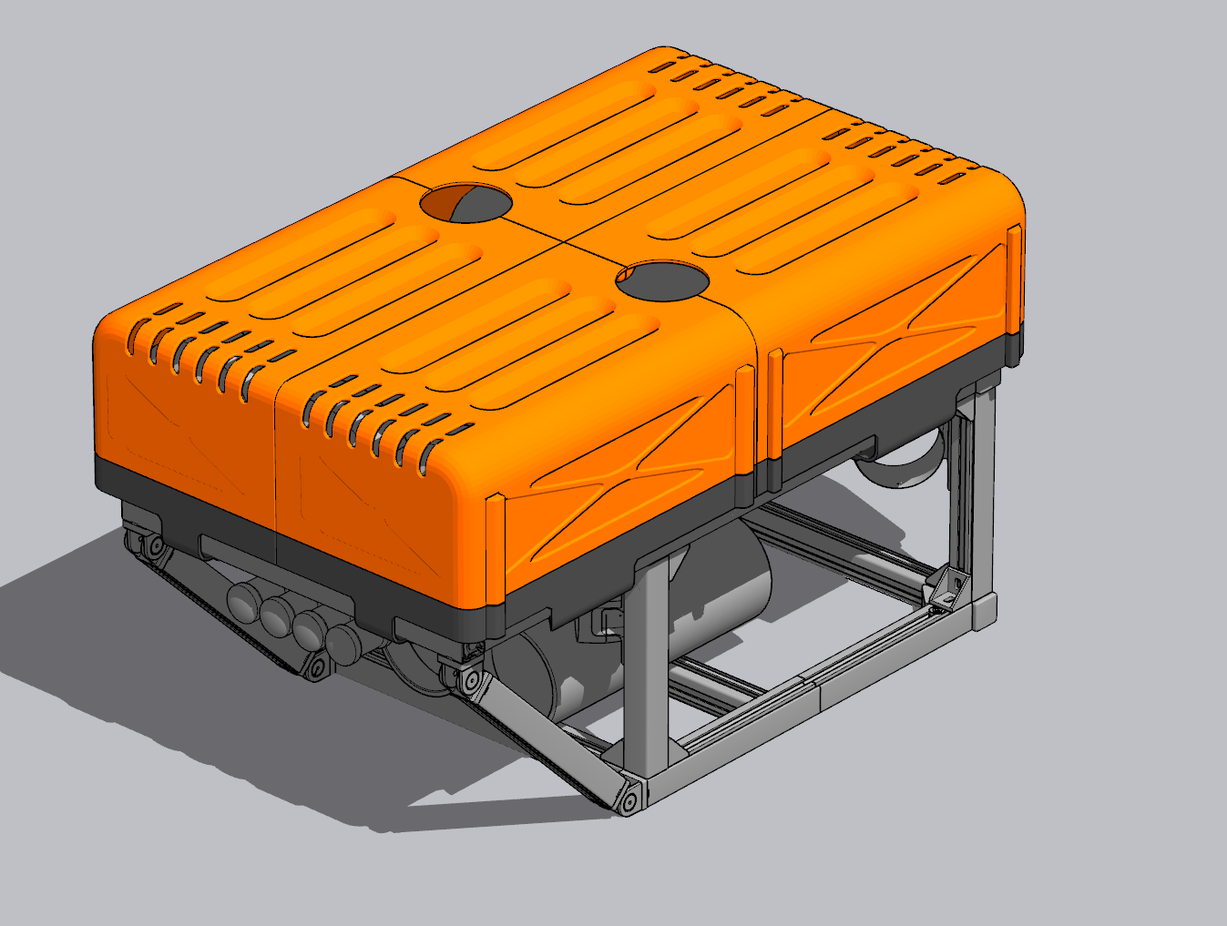
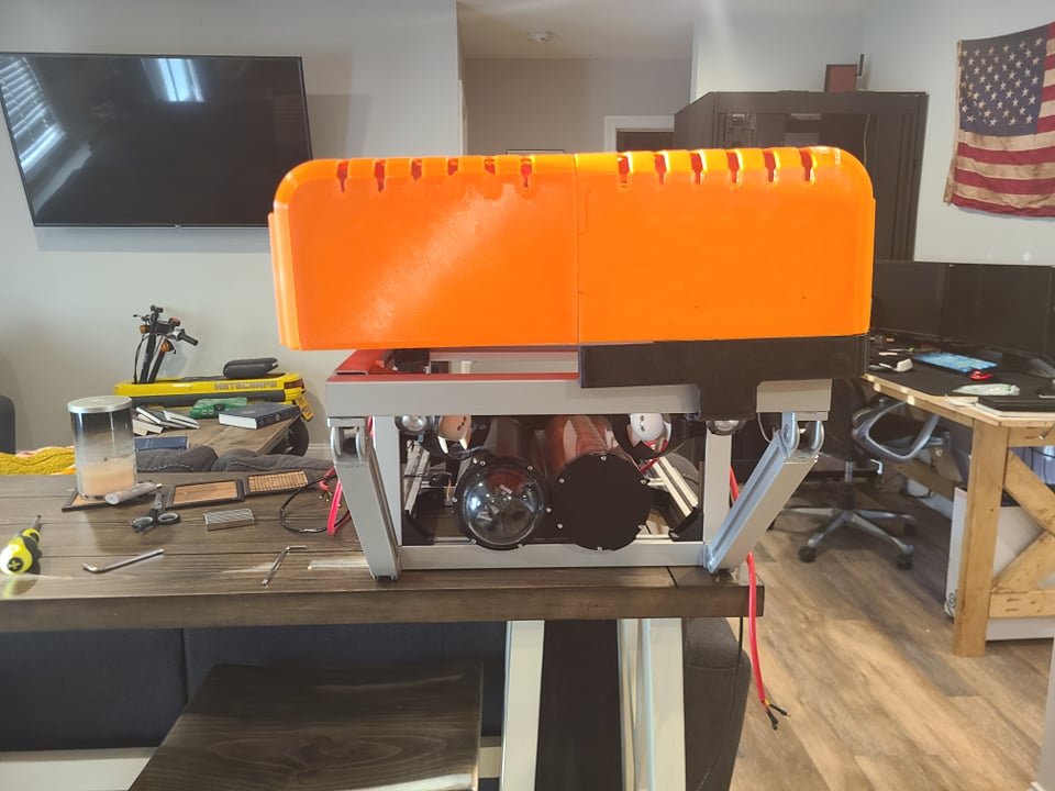
Ballast Cover
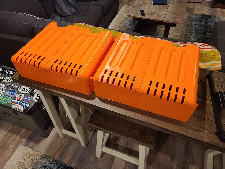
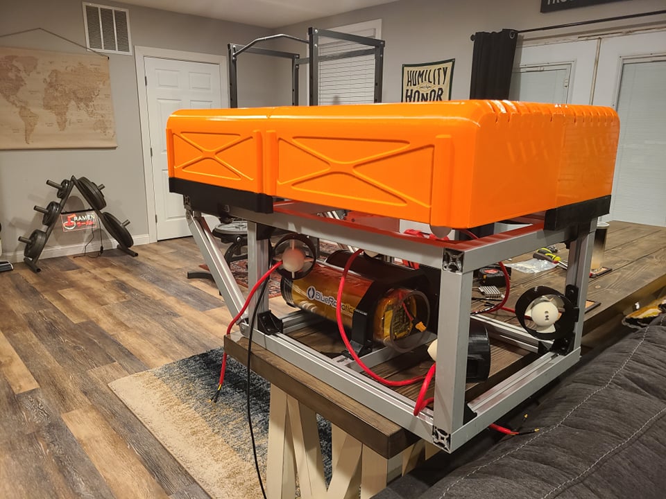
A friend helped me brainstorm some design ideas for a 3d printed cover for the ballasts. His art station can be found here: https://www.artstation.com/rhen. After a few hours he had come up with the following models. I am very happy with how this part of the project has turned out. The cover will be held to the 3d printed brackets by magnets. The cover was split into 4 parts so it could fit on my cr10-v2. Each corner piece at first was to take 4.5 days to print. I ordered some 1mm nozzles and brought the time down to just over 24 hours. Between the cover pieces and side brackets there was over 300 hours of print time (not including failures). Each cover piece is bolted together with brackets on the inside then epoxied at the seams. It will eventually be coated in epoxy resin before final install.
Next steps
Designing brackets for the ballast system and sourcing parts is next on the list. After that it is final wiring then test dive! Stay tuned for part 4 where hopefully we will do a first power on test and start configuring software. Thanks for stopping by!
comments powered by Disqus